Contadores en lógica digital – acervo lima 7490 decade counter circuit (mod-10) designing » counter circuits F-alpha.net: experiment 5
State Diagram Of 3 Bit Synchronous Counter
Mod 5 counter circuit diagram
Solved using the following schematic (mod 10 counter) as a
Wiring a relay arduinoCircuit diagram of mod 6 counter 17. the bcd (mod10) synchronous up counter circuit constructed with dModulo 6 counter design and circuit.
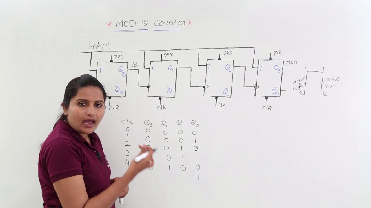
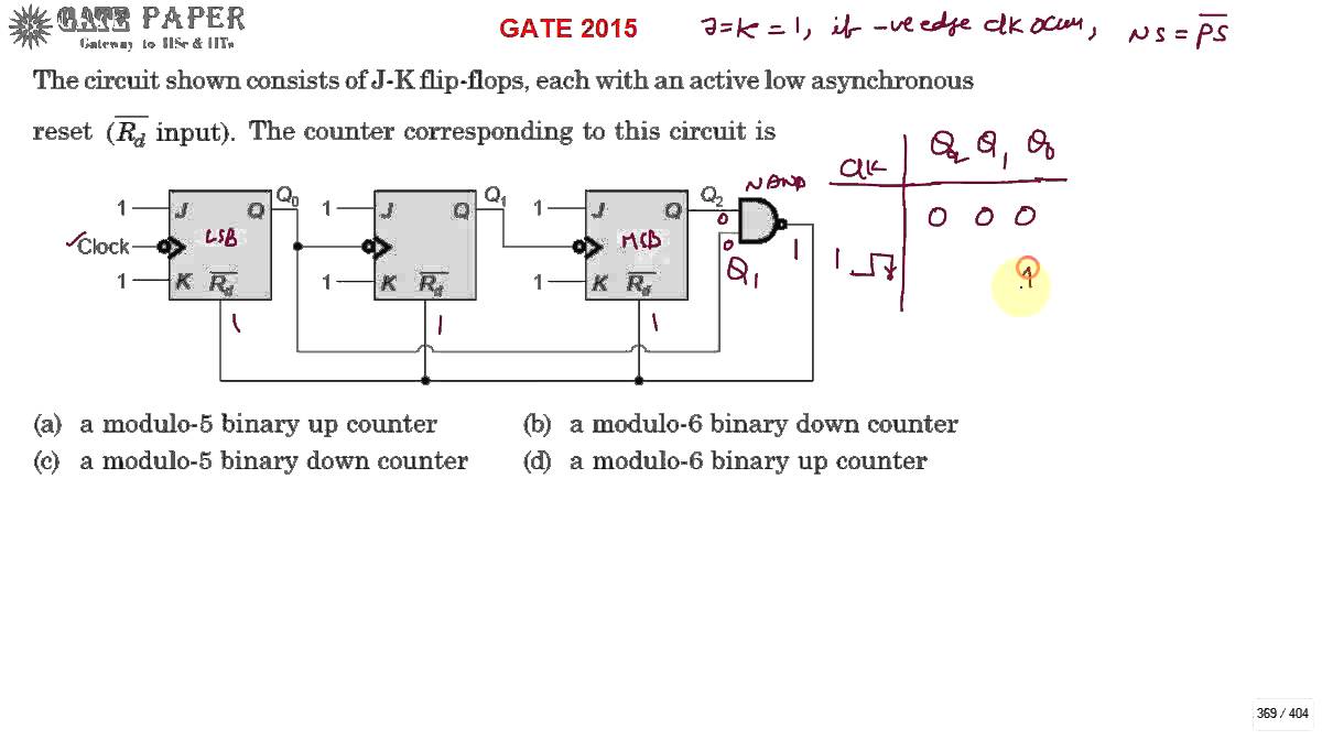
Mod 12 counter circuit diagramCircuit diagram of mod 6 counter Solved turn this mod-16 counter to mod-12 counter.show theState diagram of 3 bit synchronous counter.

Simple counter circuit diagram
Counter mod table truth counters modulo modulus truncatedCircuit diagram 4 bit binary counter Mod 6 counter circuit diagramMod counters are truncated modulus counters.
Counter asynchronous decade countMod counters are truncated modulus counters Relay module 8 channel 5vAsynchronous counter as a decade counter.

Counter segment circuit digit two ic diagram 4026 display using cd4026 555 decoder led numbers
Mod counters are truncated modulus countersCounter modulo synchronous reset schematics transcriptions 2: asynchronous counter modulo 5.Mod 10 counter circuit diagram.
Counter mod diagram timing counters modulus tutorials truncatedSynchronous bcd mod10 flops constructed murat fig19 Digital counter circuitMod 4 counter circuit diagram.

Mod 12 counter circuit diagram
Mod synchronous counter using jk flip flopCounter circuit modulo divide mod digital flip using flops counts three type petervis dictionary terms What is mod counters : design mod – n synchronous counterAsynchronous modulo.
Two digit counter circuit using 7 segment and ic 4026Counter 7490 decade circuits Bcd ripple counter (with simulation)Solved include the circuit diagram for your mod-16 counter.
Here the circuit diagram of 12v / 20a regulated dc power supply using 5
Supply power 12v 20a dc regulated circuit diagram regulator transistor voltage mj2955 using 15v board here pieces output charger giveCounter mod diagram circuit digital flip mod10 experiment electronics alpha output flops reset Counter counters modulus truncatedCircuit for mode 12 operation.
.