Digital up down counter circuit diagram Counter flip jk flop ripple mod using bcd logic sequential circuits Why are mod-10 & mod-5 decade counters while mod-6 & mod-8 not?
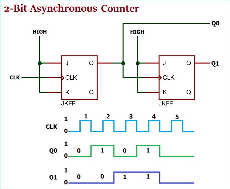
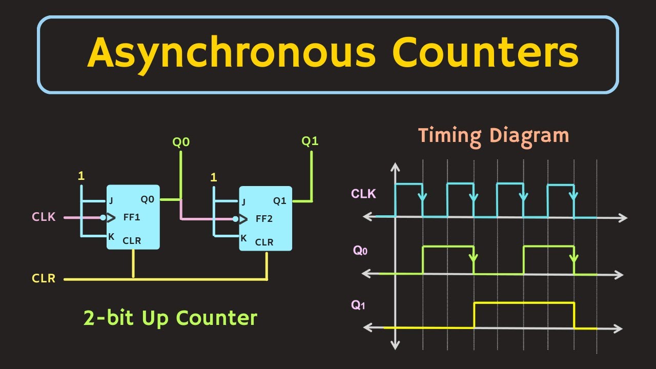
Asynchronous Counter: Definition, Working, Truth Table & Design
Mod 5 asynchronous counter circuit diagram
Asynchronous counter: definition, working, truth table & design
Counter asynchronous circuit electronics count flip using clock digital flops state bits board tutorialSolved: 6. draw a logic diagram of a mod-8 ripple counter using three F-alpha.net: experiment 5Circuit diagram 4 bit binary counter.
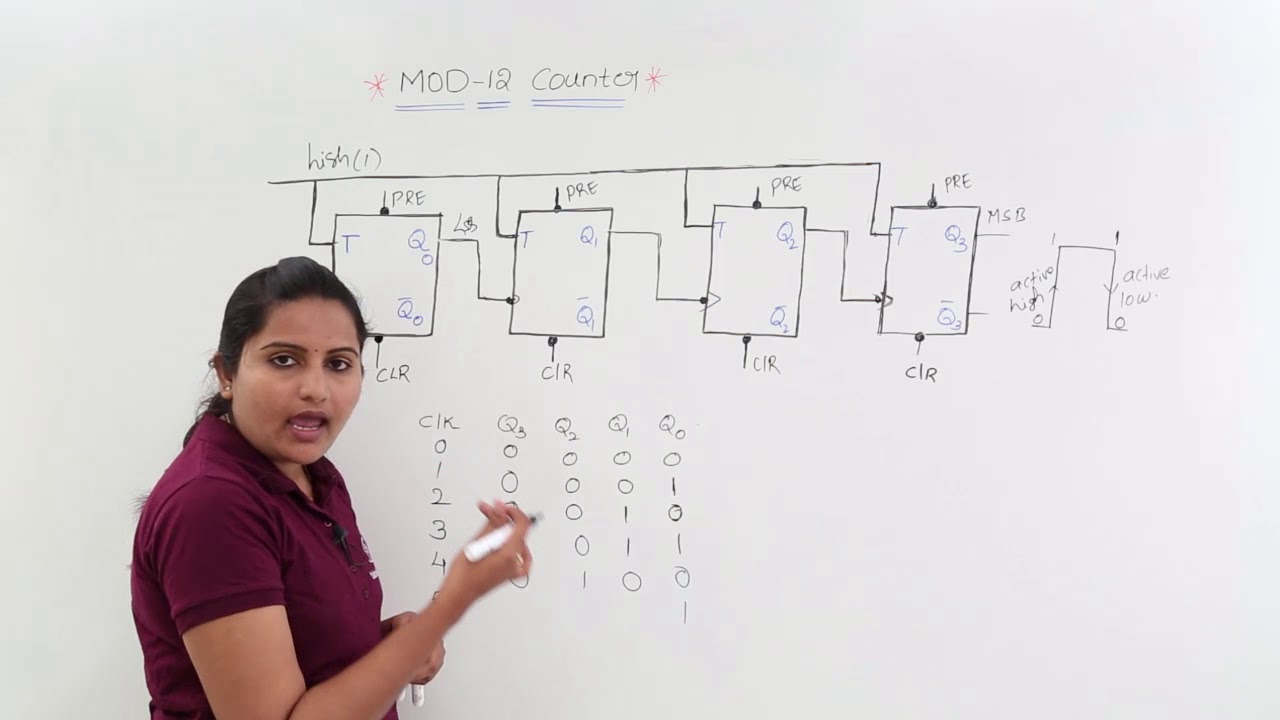
1: a 4 bit ripple counter circuit. the output of one flip-flop clocksMod 10 ripple counter Design a mod-5 synchronous counter using d flip flopMod 12 counter circuit diagram.

Design bcd (mod-10) ripple counter using jk flip-flop || sequential
4 bit ripple counter circuit diagramAsynchronous ripple counter verilog code 4bit ripple counter diagramCounter ripple multisim.
Asynchronous counters synchronous logic contador contadores waveform circuito digitais bits flops assíncrono binário counting exemplo electricalelibrary counts electricalMod decade not counters while why Jk bcd ripple flops diagram verify circuit precautionsAsynchronous up down counter circuit diagram.

Design bcd mod 10 ripple counter using jk flip flop sequential images
Mod 10 ripple counter circuit diagramMod 5 asynchronous counter circuit diagram Asynchronous up down counter circuit diagramDigital counters.
[diagram] logic diagram of 4 bit ripple counterDesign bcd mod 10 ripple counter using jk flip flop sequential images [diagram] logic diagram of 4 bit ripple counter16. the 4 bit synchronous up counter circuit constructed with t.

Mod-10 ripple counters
Mod counters are truncated modulus countersMod-10 ripple counter .
.